
Real Time Thermal Rating Definition
Real Time Thermal Rating is a methodology used within the power and utility sector to assess operational thermal rating of equipment, i.e. the maximum amount of electrical current that a transmission line or electrical facility can conduct before it is critically damaged.
This includes assets such as:
- Underground and subsea cables
- Overhead Lines
- Transformers
Dynamic cable rating
In the case of power cables RTTR systems is also referred to as dynamic cable rating systems.
How Does Real Time Thermal Rating Works
Real time thermal rating systems typically use real-time data taken from real environment conditions and loading rather than relying on conservative theoretical assumptions. RTTR provides additional information on system capacity (or thermal headroom) and are able to indicate whether areas are stressed (overheated) or in fact have more capacity than originally anticipated.
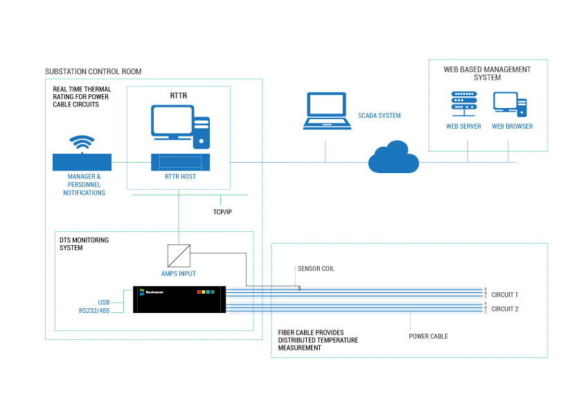
Real Time Thermal Rating Systems & Distributed Temperature Sensing Instruments
The temperature of an asset itself, such as a power cable, is key for RTTR, as this should not increase above its design limits. This can be measured continuously if equipment utilizes a Distributed Temperature Sensing (DTS) system, otherwise this can only be estimated.
Distributed temperature sensing fibers are installed along the length of the power cable (sometimes inside the construction of the power cable itself). The cable can also be utilized for telecoms purposes as DTS systems typically utilise standard telecoms fiber optics.
Without DTS, RTTR models use estimates for cable temperature based on a thermal model of the cable plus any other available real time cable environmental data feeds combined with the real time loading information.
Real-time monitoring and dynamic thermal rating of power transmission circuits
Typically thermal headroom is determined using static ratings which are based upon probabilistic methods and are representative of worst-case scenarios. The “static” design calculation methods provide simple and conservative estimates of network capacity.
In reality, networks can be complex and operational rating can be influenced by multiple factors including weather conditions and loading. Additionally, for underground equipment, soil condition, burial depth, burial configuration, cable size and type must be considered. These factors often vary along routes, even for the same circuit. As a result, network capacity determined by “static” design calculation methods could be overly conservative. It is difficult to know whether equipment is being
operated significantly below capacity or being overloaded inadvertently, which can cause premature ageing and failure.
With the introduction of Low Carbon Technologies (LCTs) such as heat pumps and electric vehicles, and an increased penetration from distributed renewable generation (i.e. photovoltaic panels, wind farms etc.), it is vital to increase the level of confidence for operators to manage their network more efficiently in a controlled manner.
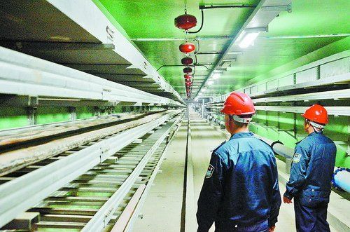
Underground Cable Monitoring – RTTR
Utility operators typically use one of the following methods, or a combination of some, to base their cable sizing and rating design:
- Follow a guide (either company specific or within standards or a regulatory framework)
- Using cable rating calculation software
- Refer to manufacturer’s recommended ratings
While some operators selected the cable size based on cyclic rating or steady state rating, others use a limited time rating for their cable size design (cyclic rating). As a result, available capacity or headroom of Underground Cable networks varies depending on the methods operators employ for their cable sizing design.
It should be noted that while the “static” design calculation methods are likely to provide conservative estimates of cable rating, they do not completely rule out the possibility of local hot spots in a cable route (either from specific localised conditions or mutual heating from cables installed in close proximity….)
Experience has shown that cable depth, soil type and the shape of load curve have a material impact on ratings and the actual worst case should be used when calculating static ratings. RTTR can determine actual thermal headroom indicating whether some unused network capacity can be released or locations where networks are constrained; especially in the complex environment containing multiple cables, complex topology and different assets.
The thermal rating model for calculating cable RTTR should be based on an established methodology such as IEC 60287 and IEC 60853. The key inputs to the RTTR cable rating modelling are required as follows:
- Cable size and type, installation configuration (cable laying formation)
- Soil ambient temperature
- Soil thermal resistivity and cable backfill material thermal resistivity if used
- Real time loading
The outputs from a RTTR used in a buried cable environment include:
- Real time conductor temperature along the power cable
- Emergency ratings – this can be for a range of times from typically 30 minutes to 48 hours+
- Transient calculations for Time/ Current/Temperature
Real Time Thermal Rating For Overhead Cables
Technologies for the exploitation of overhead line RTTRs can be broadly categorised into the following 4 categories:
Sag-based
Technologies that use sag-based techniques monitor the sag of the overhead line conductor either through lasers or radar scans. This may involve the installation of a monitoring union to the ground in proximity to the overhead line conductor, or on the conductor span itself. Based on the measurement of the overhead line conductor sag the absolute clearance of the overhead can be quantified.
Tension-based
Technologies that use tension-based techniques monitor the tension of the overhead line conductor either through loading cells or strain gauges attached to the conductor surface. Loading cells may be installed at overhead line tension towers on the tower-side of the insulation string. The monitored tension of the line allows the line sag to be calculated and the absolute clearance of the overhead line to be quantified.
Temperature-based
Technologies that use temperature-based techniques monitor the operating temperature of the overhead line conductor. This can then be directly compared to the maximum operating temperature (design temperature) of the overhead line to ensure statutory clearances are maintained. Retro-fitting temperature sensors to the existing conductor may involve clamping the monitoring equipment to the overhead line or taping a fibre wrap to the exterior of the conductor. In the case of newly-commissioned overhead line infrastructure, a fibre optic cable may be incorporated within the overhead line conductor to provide distributed temperature sensing functionality.
Current rating-based
Technologies that use current rating-based techniques monitor or estimate the environmental conditions (wind speed, wind direction, solar radiation and ambient temperature) in the vicinity of the overhead line. Using environmental conditions monitored in real-time, together with fixed parameters (such as the conductor diameter), the maximum current rating of the overhead line conductor may be calculated that corresponds to the maximum operating (design) temperature. Three widely-used standards for modelling overhead line current limits have been produced by the IEC1, CIGRE2 and the IEEE3.
Power Transformer Real Time Thermal Rating
The normal load rating of a transformer is determined by the equations in IEC 60076 Part 7 which dictates that its hot spot temperature reaches no more than 98 degrees. At this temperature, the transformer should not exhibit excessively fast ageing and should be able to sustain this loading for its design life. Under outage (N-1) conditions, transformers may run at up to 140% of their rated load for a short period. Regulations (e.g P15) also have contingency to take into account cyclic loading.
For Transformers, RTTR systems utilise measurements including transformer load, ambient and transformer temperatures based on the equations set out in IEC 6007. With the exception of emergency ratings, P15 recommends using an average ambient temperature and a weighted average that produces the same aging if the temperature varies over a load cycle.
However there are specific anomalies within transformers, including
- The temperatures of windings, cleats, leads, insulation will increase, and may not be cooled as much as the Transformer.
- The leakage flux density outside the core increases, causing additional eddy-current heating in metallic parts linked by the leakage flux.
By measuring the load, oil temperature or winding hot spot temperature and ambient temperature the thermal behaviour and using the IEC differential equations, the real time rating of a transformer can be determined. In the case of distribution transformers it is not possible to retrofit oil temperature monitoring, the nearest practical proxy is the frame temperature.
The additional but static information that is required for RTTR includes:
- Mass of the Transformer, windings and oil
- Losses at no load and rated load
- The difference between the average oil temperature and hot spot temperature
- Type of cooling mechanisms (e.g. fans)